
Understanding surface code compatible high-fidelity supercoducting universal quantum gates
Published:
This post is a summary of the paper ``Supercoducting quantum circuits at the surface code threshold for fault tolerance” by Barends et al. The goal of this blogpost is to focus on the key messages conveyed in the paper, and not to provide a complete detailed explanation.
Introduction
Quantum algorithms like Shor’s factoring, Grover’s search and Deutsch-Jozsa algorithms have demonstrated the advantage of quantum computers over classical ones in terms of computational time complexity. However, the presence of noise in quantum circuits limits the types of problems that can be solved using quantum hardware. This gives rise to a fundamental question - is it possible to perform computations using noisy components with an arbitrarily small error? The ability to perform quantum computations with arbitrarily high reliability using noisy components is called fault-tolerant quantum computing (FTQC), which can be achieved by encoding logical qubits over a large number of physical qubits using a suitable quantum error correction (QEC) code. In this context, the threshold theorem of FTQC states that if the fidelity of each component is above a certain threshold, then it is possible to achieve arbitrarily small computational error using a suitable QEC code (Aharonov et al). This threshold fidelity depends on the specific QEC code used (among several other factors). Among QEC codes, surface codes have gained immense popularity due to their modest threshold fidelity requirements, and simple planar architecture realizable on the current quantum computers. Specifically, FTQC using surface code has three main requirements: gate fidelities greater than 99%, the ability to establish coupling between adjacent qubits to detect and correct errors, and scalable architecture to accommodate a large number of logical qubits.
Prior to (Barends et al), no physical realization of a quantum system could meet all the three aforementioned requirements of surface code based FTQC. A 3-qubit transmon based quantum processor was realized in (Chow et al), but the 2-qubit gate fidelity was 96%. Some non-superconducting qubit realizations could achieve fidelities higher than 99%, for example, nuclear magnetic resonance with 99.5% (Ryan et al) and ion-traps with 99.3% fidelities (Benhelm et al), but unfortunately, they are difficult to scale.
The main contributions of (Barends et al) are as follows: A simple linear array of \tu{nearest-neighbor capacitively coupled} Xmons (cross-shaped transmons) is proposed - since Xmons belong to the family of superconducting qubits, they can be fabricated on a chip making them \tu{scalable}. In this context, scalability implies the ability to accommodate a large number of qubits without too much overhead. Secondly, a novel implementation of 2 qubit gate by fast adiabatic qubit frequency tuning is proposed, which helps in achieving a high fidelity of 99.4% for a two-qubit gate (C-Z gate) - this is greater than the fault-tolerant threshold for surface code protected quantum circuits, and the fidelity of one-qubit gate is improved from 99.7% in prior work (Chow et al) to 99.92%, forming a \tu{universal set of gates} (\(R_x(\theta)\), \(R_y(\theta)\), and controlled-Z) with \tu{high fidelity}. Therefore, it is a first step towards achieving a fault-tolerant quantum computer.
Circuit architecture
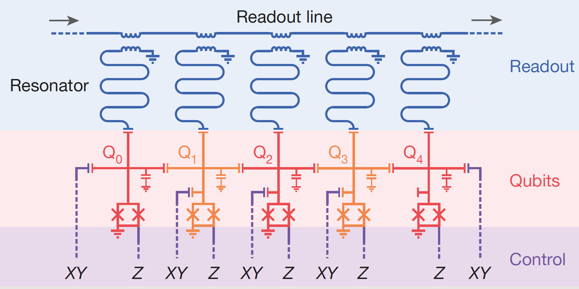 Fig 1. Architecture of an Xmon based circuit
The quantum circuit contains a linear array of 5 Xmons. Each Xmon has a cross-shaped structure with 4 arms – one arm for control, 2 for coupling with adjacent Xmons to the left and right, and one for readout. Unlike the original transmon qubit proposed in (Koch et al), Xmon is grounded with one of its capacitor pads. Every Xmon couples capacitively to the adjacent Xmons - this is another key difference with the 3-qubit transmon circuit proposed in (Chow et al), where a bus resonator was used for coupling. The simple modular architecture of the superconducting circuit implies that the scaling is straightforward - merely concatenate Xmons in a linear array. Single qubit gates can be implemented as follows: X rotations can be implemented using resonant microwave pulses, and Z rotations by using flux bias current. Readout is done using a single line by frequency division multiplexing and dispersive readout.
The dispersive readout is performed as follows: In Figure 1, each qubit has a dedicated readout resonator capacitively coupled to one arm of the Xmon. The resonant frequency (\(\omega_r\)) of the resonator is detuned far away from the qubit transition frequency (\(\omega_{01}\)), in particular, the detuning is large relative to the coupling constant $g$, which is called the dispersive regime. Now, due to coupling with the qubit, the overall resonant frequency depends on the qubit transition frequency, which is the key ingredient allowing qubit readout. In order to measure the qubit, we interrogate the resonator by applying a microwave pulse close to the resonance frequency and by measuring the reflected signal. In the Xmon architecture in Figure 1, there is only a single readout line that contains frequency division multiplexed readout pulses for each qubit.
Implementation of high fidelity C-Z gate by fast adiabatic frequency tuning
The novelty of the paper (Barends et al) is the realization of a high-fidelity controlled-Z gate by fast adiabatic tuning, which is explained in this section. First, let us describe the spectrum of a joint system of two Xmons. Suppose the energy levels of a joint system of two Xmon qubits A and B with different excitation frequencies are as shown in Figure 2. Let \(\alpha\) denote the detuning of qubit A with respect to qubit B. When the qubits are not coupled, the energy levels \(\vert 20\rangle\) and \(\vert 11\rangle\) cross over at a specific detuning frequency. Thanks to anharmonicity and different excitation frequencies of the two qubits, the detuning frequencies corresponding to the cross-over points are different for the pair \(\vert 20\rangle\), \(\vert 11\rangle\) and the pair \(\vert 10\rangle\), \(\vert 01\rangle\). However, if the qubits are coupled, then they hybridize and the energy levels don’t cross as shown Figure 2(c).
For a quantum system at the \(n^{th}\) eigenstate, the adiabatic evolution of the Hamiltonian results in the system maintaining its presence in the \(n^{th}\) eigenstate, concurrently acquiring a phase factor (called as Berry phase). Suppose the initial state of the qubit pair is \(\vert 11\rangle\), then applying a flux bias current results in a constant flux, which detunes qubit A relative to qubit B such that \(\vert 20\rangle\) is aligned with \(\vert 11\rangle\). Since the qubits are coupled, the qubits perform Rabi oscillations between \(\vert 11\rangle\) and \(\vert 20\rangle\), while acquiring a phase of \(i\) in every transition (half oscillation). The oscillation frequency is equal to the difference in the hybridized energy levels, which is proportional to the coupling constant \(g\) between the two qubits. Now, if we wait for a fixed duration of time (around \(43\) ns, which includes the Gaussian phase for switching on, flat duration, and the Gaussian switch off phase), the state \(\vert 11\rangle\) acquires a negative phase. Now, turning off flux bias current reverts the qubit A back to the original detuning. At the end of this adiabatic trajectory, the state \(\vert 11\rangle\) will have acquired a negative phase (Please refer to Figure 3 for illustration).
This happens only for state \(\vert 11\rangle\) and all other states remain unchanged since they do not interact with any other energy levels – in other words, this is an implementation of a controlled Z operation. The entire gate operation completes in 43 ns, which is a significant improvement over its transmon predecessor which took about 350 ns \cite{barends2013coherent} for a two-qubit gate operation. The improvement in gate operation time is due to direct capacitive coupling between the neighboring qubits (with a large coupling frequency of \(g/2\pi = 30\) MHz) instead of each qubit capacitively coupling to a common bus resonator. This additional degree of separation between qubits in (Chow et al) resulted in a smaller coupling constant. In (Barends et al), a faster gate means that there is less room for dephasing, which is one of the primary reasons for the high fidelity of this realization of the CZ gate.
One may ask, can we make this operation even faster? - attempting this would lead to the following issues: the detuning trajectory may not be adiabatic, which could worsen the leakage to a non-computational state \(\vert 20\rangle\). Upon reaching the avoided crossing, the controlled-Z gate duration is also limited by the coupling constant between the qubits (gate duration is inversely proportional to \(g\)). Therefore, to achieve high fidelity of a two-qubit gate, we need to operate fast enough to not let the quantum state decohere, and at the same time slow enough to maintain adiabaticity (minimize the leakage to non-computational state). This can be achieved by optimizing the detuning, phase accumulation and reverting trajectory as shown in Figure 4.
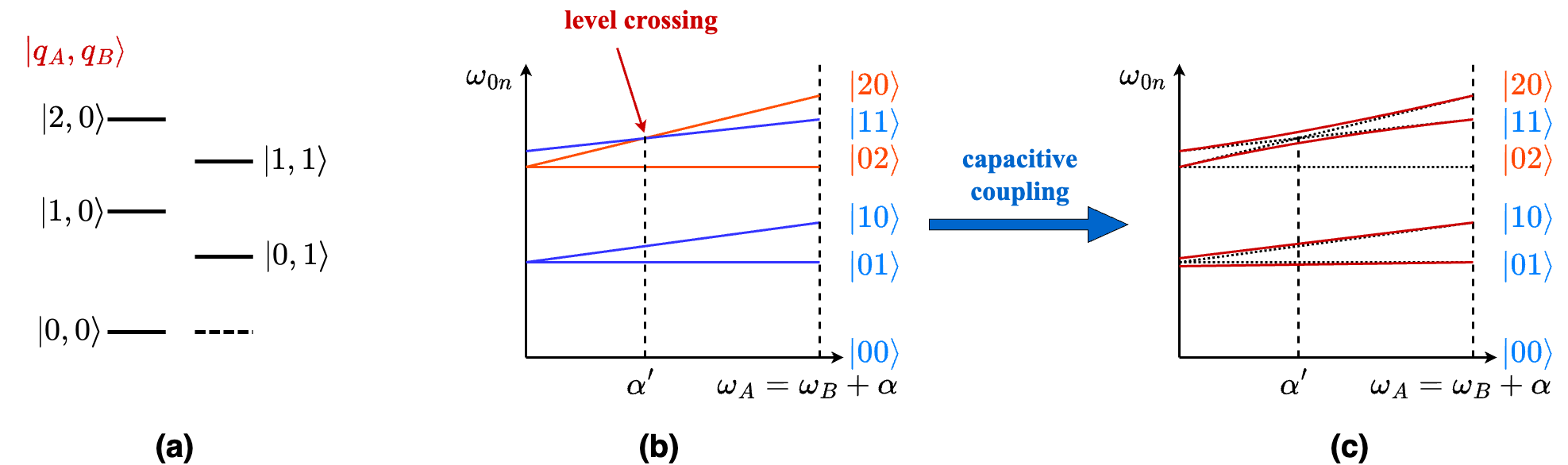 Fig 2. Energy levels of capacitively coupled nearest neighbor Xmons. a) Energy levels with no detuning, b) Spectrum of joint two-qubit system (uncoupled), and c) Spectrum of joint two-qubit system with capacitive coupling.
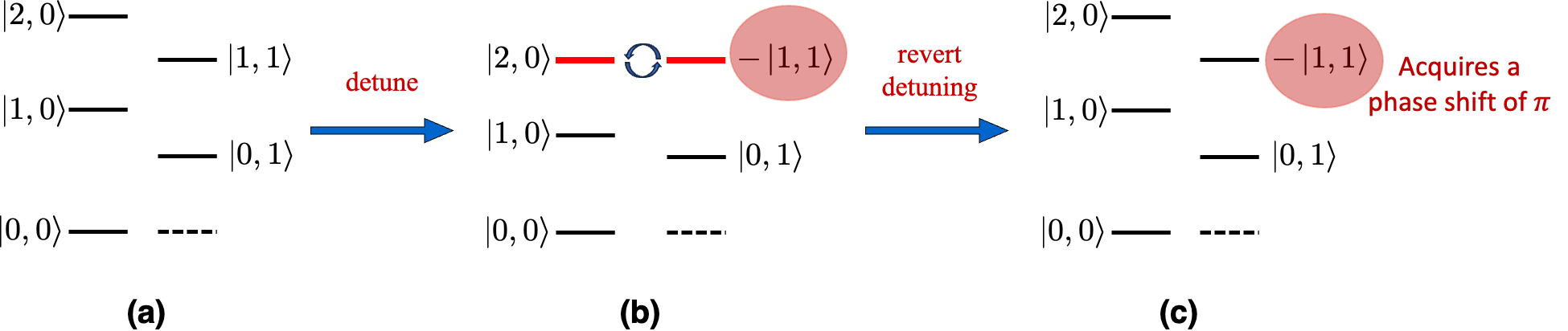 Energy levels at every stage of CZ operation and acquisition of phase \(=\pi\) by the computational state \(\vert 11\rangle\).
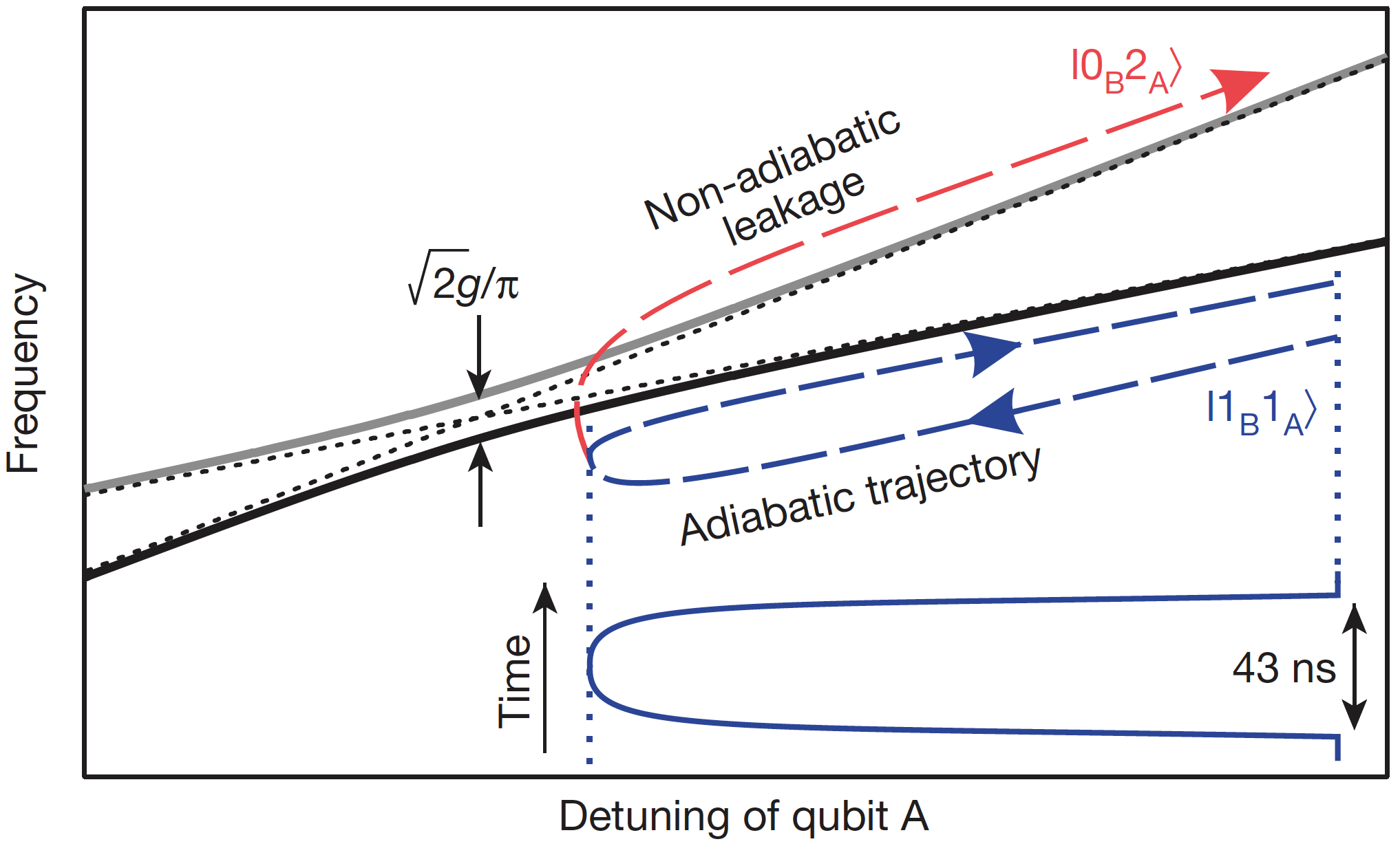 Fast adiabatic trajectory to implement a CZ gate shown by dashed and directed dark blue curve (labeled as \(\vert 1_B 1_A\rangle\)).
Results
A straightforward way to evaluate the gate fidelity is to arbitrarily initialize the qubits and perform gate operation under evaluation followed by measurement. However, this procedure does not provide true fidelity of the gate since it does not consider the errors in state preparation and measurement. Therefore, we need a way to isolate the fidelity of the gate from other sources of error.
Benchmarking of the fidelity of gates is performed in the following manner: first, consider a reference circuit that performs random Clifford gates $m$ times followed by a recovery gate that undoes all the previous $m$ gates resulting in an overall identity operation (supposing the gates are noiseless). The fidelity of this sequence of gates forms a reference that captures the initialization and measurement errors. Secondly, the gate under evaluation, is interleaved with the same set of random Clifford gates $m$ times, and a final recovery gate (different from the reference circuit) is appended at the end of the chain of gates such that the entire operation is equivalent to identity. Now, the gate fidelity can be inferred from the difference in fidelities between the reference circuit and interleaved circuit. In Figure 5, x-axis is the depth of the circuit, y-axis is the sequence fidelity. Black solid curve corresponds to 100% fidelity and the dashed curve to 99% fidelity. The two-qubit CZ gate has a fidelity > 99% at all depths.
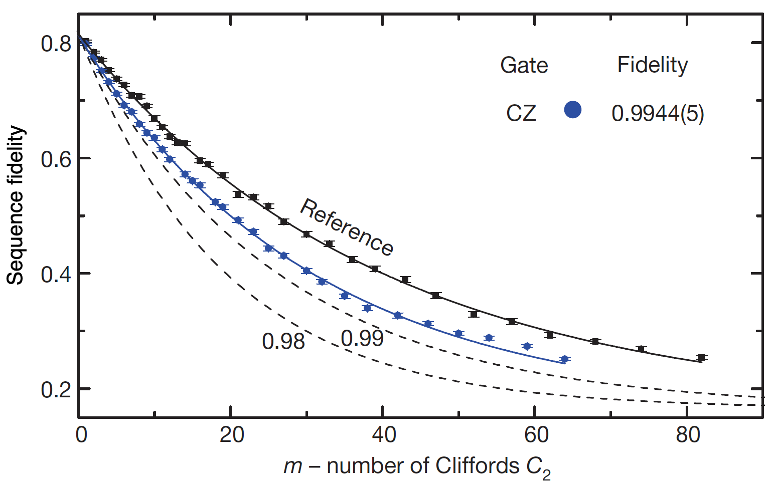 Sequence fidelity vs circuit depth (\(m\)). The sequence fidelity of CZ gate is sandwiched between the sequence fidelity of reference circuit (black solid curve) and sequence fidelity of 99% (black dashed curve). Therefore, CZ has a circuit fidelity of > 99%.
Conclusion
In this blogpost, we reviewed an Xmon-based superconducting quantum circuit, which demonstrated high gate fidelities for a universal set of quantum gates. We also discussed the process of fast adiabatic qubit frequency detuning to implement a CZ gate, which resulted in improving the state-of-the-art two-qubit gate fidelity to 99.4%. Consequently, a universal set of gates could be synthesized that exceeded the threshold fidelity required by the surface code. The simple and modular Xmon architecture helped in creating a linear array of qubits, which is potentially scalable beyond 5 qubits. This work brought us a step closer to the goal of achieving a fully fault-tolerant quantum computation.
Some open questions not addressed by this work are as follows: First, to implement surface code, a linear array is not sufficient - a 2D array of data qubits and ancillas in a checkerboard pattern is required. The authors of paper (Barends et al) propose a 2D architecture (in supplementary material), but without performance analysis. Therefore, practical extension of the current Xmon architecture is still an open (most likely engineering) challenge (at the time of publication of (Barends et al)). Second, to perform meaningful quantum computations we need long-range coupling between logical qubits (formed by patches of several physical qubits) - the routing between logical qubits is not addressed in the paper, which makes realizing a truly fault-tolerant quantum computer still a work in progress.